
General Hardware
Bridging
MB / MBG
Reference Series: NCA
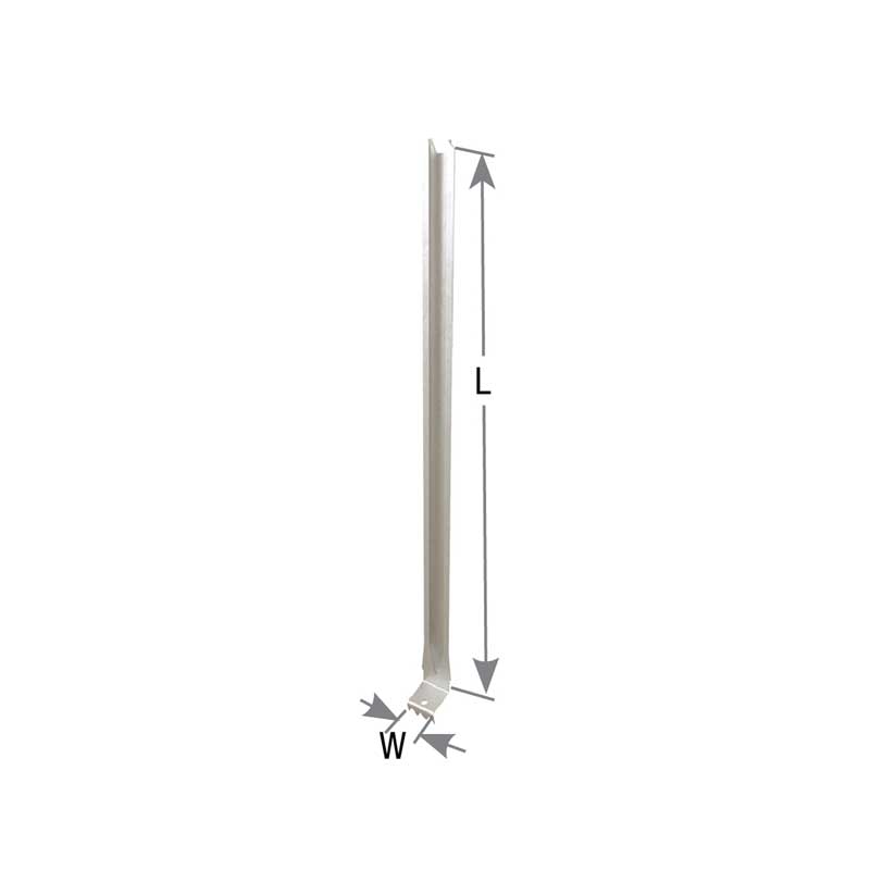
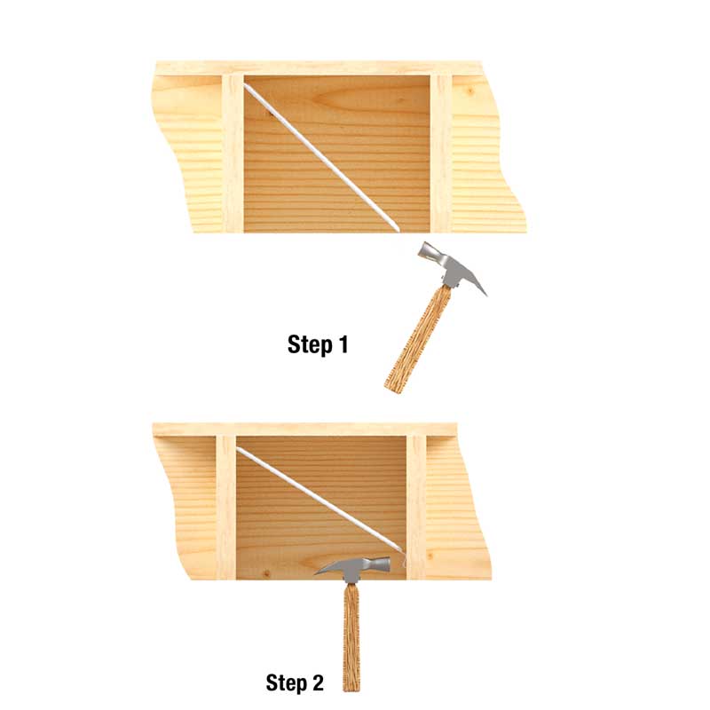
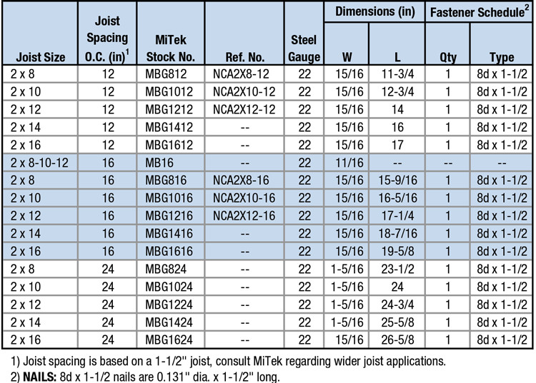
MBG – Grip tooth bridging. Features special teeth which grip joists and provide easy single-nail installation. Can be installed after subfloor is in place.
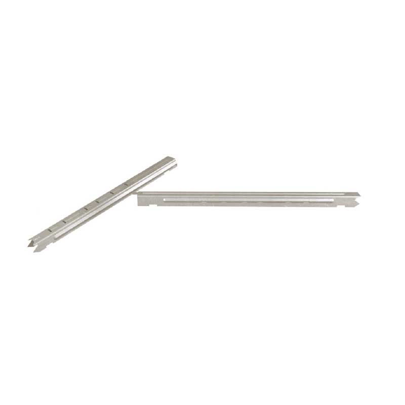
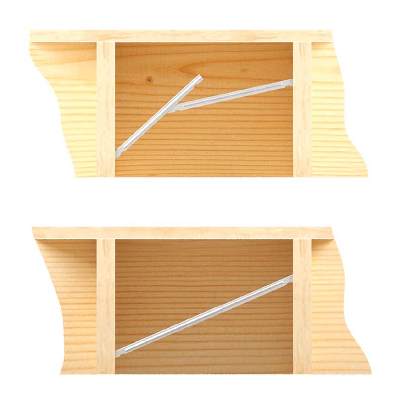
MB16 – Snap-on, no-nail bridging can be placed in existing floor systems where joist movement is suspected. Two-piece construction creates a solid diagonal brace against joist movement.
MB16 – Snap-on, no-nail bridging can be placed in existing floor systems where joist movement is suspected. Two-piece construction creates a solid diagonal brace against joist movement.
Materials: See Load Table
Finish: G90 galvanizing
Code Reports:
View Code Report Table
Installation
- Use specified fasteners in models with fastener requirements.
- For all models – Bridging should be installed on floor joists with a nominal depth-to-thickness ratio of 5 to 6 or more (2015 National Design Specification for Wood Construction; Section 4.4.1). Bridging units should be installed in pairs at intervals of 8′ or less. Bridging pairs should form an “X” between joists; leave a slight space between the units to avoid noise-generating contact. Follow specific installation instructions below for particular models.
- MBG – May be installed before or after sheathing. Position the unbent end of the bridging unit near the top of the joist and drive prongs into wood with a hammer blow to the heel of the bent end. Wedge bent end near the lower edge of the opposite joist, set teeth into wood with hammer blow. Nail holes are provided at the bent end if prongs are damaged during installation. Fully seat nails to avoid any movement against the bridging and subsequent floor noise.
- MB16 – Two-piece unit is shipped as one piece. Bend unit in center up and down to break into two pieces. Slide narrower piece inside wider piece, setting the end tab into slot appropriate for joist spacing. Setting one prong end near the top of one joist and the opposite prong end near the bottom of the opposite joist, pull down on the center of the bridging until the wider piece snaps into place over the narrow piece and creates a rigid, one-piece bridging unit. Wear gloves during installation.
Need Help or Have a Question? Contact Customer Service or Call 800-328-5934
MBG Grip Tooth Bridging
Code Report Table
3-View Product Drawings
| MiTek Stock # | Download or View Files | |||
|---|---|---|---|---|
| MBG1012 | DWG | DXF | View Image | |
| MBG1016 | DWG | DXF | View Image | |
| MBG1024 | DWG | DXF | View Image | |
| MBG1212 | DWG | DXF | View Image | |
| MBG1216 | DWG | DXF | View Image | |
| MBG1224 | DWG | DXF | View Image | |
| MBG1412 | DWG | DXF | View Image | |
| MBG1416 | DWG | DXF | View Image | |
| MBG1424 | DWG | DXF | View Image | |
| MBG1612 | DWG | DXF | View Image | |
| MBG1616 | DWG | DXF | View Image | |
| MBG1624 | DWG | DXF | View Image | |
| MBG812 | DWG | DXF | View Image | |
| MBG816 | DWG | DXF | View Image | |
| MBG824 | DWG | DXF | View Image | |
Application Drawings
| MiTek Stock # | Download or View Files | ||||
|---|---|---|---|---|---|
| MBG1012 | Typical | DWG | DXF | View Image | |
| MBG1016 | Typical | DWG | DXF | View Image | |
| MBG1024 | Typical | DWG | DXF | View Image | |
| MBG1212 | Typical | DWG | DXF | View Image | |
| MBG1216 | Typical | DWG | DXF | View Image | |
| MBG1224 | Typical | DWG | DXF | View Image | |
| MBG1412 | Typical | DWG | DXF | View Image | |
| MBG1416 | Typical | DWG | DXF | View Image | |
| MBG1424 | Typical | DWG | DXF | View Image | |
| MBG1612 | Typical | DWG | DXF | View Image | |
| MBG1616 | Typical | DWG | DXF | View Image | |
| MBG1624 | Typical | DWG | DXF | View Image | |
| MBG812 | Typical | DWG | DXF | View Image | |
| MBG816 | Typical | DWG | DXF | View Image | |
| MBG824 | Typical | DWG | DXF | View Image | |