General Hardware
Bridging
O / N
Reference Series: LTB, TB
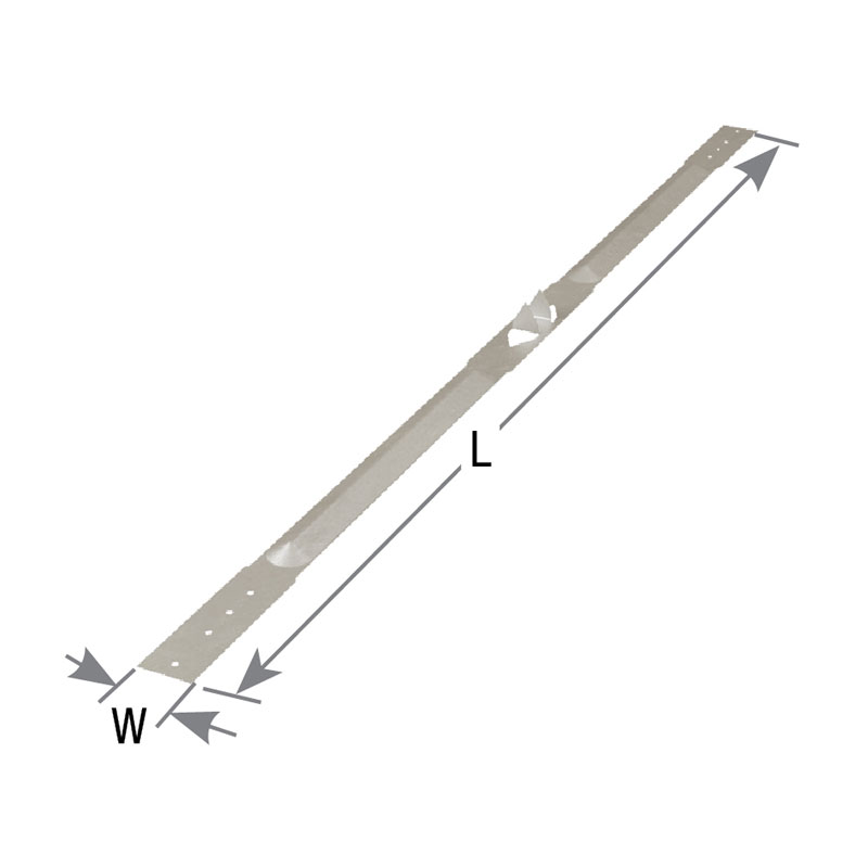
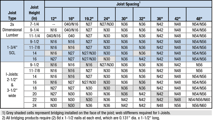
O – The O series spans three joists in under/over installation. Prong teeth in the center help reduce nailing.
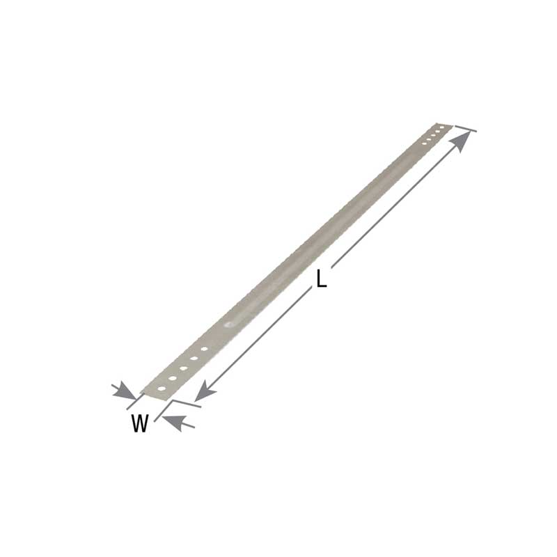
N – The N series spans two joists per unit. Can be used for bridging or bracing I-Joists. See Joist Installations table.
N – The N series spans two joists per unit. Can be used for bridging or bracing I-Joists. See Joist Installations table.
Materials: See Load Table
Finish: G90 galvanizing
Code Reports:
View Code Report Table
Installation
- Use specified fasteners in models with fastener requirements.
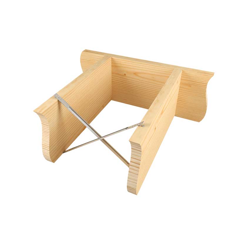
- For all models – Bridging should be installed on floor joists with a nominal depth-to-thickness ratio of 5 to 6 or more (2015 National Design Specification for Wood Construction; Section 4.4.1). Bridging units should be installed in pairs at intervals of 8-ft or less. Bridging pairs should form an “X” between joists; leave a slight space between the units to avoid noise-generating contact. Follow specific installation instructions below for particular models.
- Install prior to subfloor sheathing. Use (2) 8d x 1-1/2″ nails at each end. Fully seat nails to avoid any movement against the bridging and subsequent floor noise.
Need Help or Have a Question? Contact Customer Service or Call 800-328-5934
O Bridging

Load Tables
O / N Specification Table

Joist Installations
Code Report Table
3-View Product Drawings
| MiTek Stock # | Download or View Files | |||
|---|---|---|---|---|
| N16 | DWG | DXF | View Image | |
| N27 | DWG | DXF | View Image | |
| N30 | DWG | DXF | View Image | |
| N36 | DWG | DXF | View Image | |
| N42 | DWG | DXF | View Image | |
| N48 | DWG | DXF | View Image | |
| N54 | DWG | DXF | View Image | |
| N56 | DWG | DXF | View Image | |
| N60 | DWG | DXF | View Image | |
Application Drawings
| MiTek Stock # | Download or View Files | ||||
|---|---|---|---|---|---|
| N27 | Typical | DWG | DXF | View Image | |
| N30 | Typical | DWG | DXF | View Image | |
| N36 | Typical | DWG | DXF | View Image | |
| N42 | Typical | DWG | DXF | View Image | |
| N48 | Typical | DWG | DXF | View Image | |
| N54 | Typical | DWG | DXF | View Image | |
| N56 | Typical | DWG | DXF | View Image | |
| N60 | Typical | DWG | DXF | View Image | |